
9705 Gen 5 Remote Ready Module
Digital output level sensors for Rochester Remote Ready Dials (R3D).
Maximize your fluid level detection capabilities with Rochester Sensors remote-read R3D modules. Incorporating a remote-read system allows you to monitor your fluid or fuel levels remotely, providing a reliable, safe, and convenient solution to track usage. Utilizing the digital output from Rochester remote-read modules allows you to monitor levels in one or many tanks and is integral to any automated monitoring system.
Application
The Rochester 9705 3V module snap-fits into the recess of your existing Rochester Sensors Junior or Senior sized R3D remote-ready dial lens to provide a low power, cost-effective solution to digitally transmit fluid levels. The sensors will detect the position of the fluid level indicator in the dial it is attached to, as well as the ambient temperature. Data from the module’s integrated circuit is communicated via I2C protocol (IC to IC, bidirectional 2-wired serial bus) to the microcontroller in the end-users wired, or wireless monitoring device. Multiple 9705 R3D modules can be connected to a single monitoring circuit using unique module address configurations. 9705 Modules require a 3VDC input and offer extremely low current draw that is excellent for battery powered applications.
Información general y características
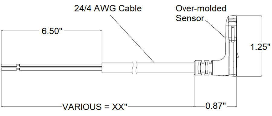
- Cable length up to 25 ft max (3 ft. standard length) with flying leads
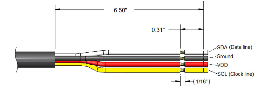
- 24 AWG – 4 conductor cable for power, ground, SDA, and SCL.
- Accuracy: Module output +/- 2% of visual dial indication. (Float gauge errors not included)
- Repeatability: +/- 1%
- Operational Voltage Range: 2.2 to 3.6 VDC (Down to 1.8V I/O Voltage for I2C lines)
- Data Output: Dial position (via magnetic flux density along X, Y, & Z axes) and Temperature
- Communication Protocol: I2C serial bus
- Resolution: 16 Bit
- Operating Current: Typical ≤ 0.1mA, Peak ≤ 1mA
- Operating Temperature Range: Dynamic -25°C to +80°C; Static -30°C to +80°C
- Storage Temperature: -40°C to +105°C
- Ingress Protection: IP69K rated
- Intrinsically safe in explosive atmospheres.
Documents
Data Sheet
Installation Instructions – Reference DS-2013
Información de pedidos
| Rochester Part Number | Descripción |
|---|---|
| 9705-ABCXXM | 9705 Product Family A – Specify orientation of module: (S=Straight, R=Right Angle) B – Specify 7-bit I2C address configuration (0=0x0C, 1=0x0D, 2=0x0E, 3=0x0F) C – Cable Type (C=1, 4 wire cable only XX – Specify length of cable for module (Standard length is 3 ft) M – Molded construction |
Product Certifications
Rochester Sensors R3D modules are certified as intrinsically safe for Class 1, Division 1, Groups C & D hazardous locations. Products are marked and approved by ETL, ATEX, UKCA, and CE. Certification and testing has been performed to the following standards:
Hazardous Locations Safety Standards
| Ordinary Locations Safety Standards | |
|---|---|
| Conforms to UL STD 61010-1 Ed.3 |
Electrical Equipment for Measurement, Control, and Laboratory Use; Part1: General Requirements *Note: for USA ordinary locations listing certification |
| Certified to CSA STD C22.2 #61010-1-12 Ed.3 |
Electrical Equipment for Measurement, Control, and Laboratory Use; Part1: General Requirements *Note: for Canada ordinary locations listing certification |
| IEC 60079-0: 2017 | Explosive atmospheres – Part 0: Equipment – General requirements *Note: For IECEx Certification |
| EN 60079-0: 2011 + C1: 2012 |
Explosive atmospheres – Part 11: Equipment protection by intrinsic safety “i” *Note: For IECEx Certification |
| EN 60079-0: 2018 | Explosive atmospheres – Part 0: Equipment – General requirements *Note: For ATEX Certification |
| EN 60079-0: 2012 | Explosive atmospheres – Part 11: Equipment protection by intrinsic safety “i” *Note: For ATEX Certification |
| UL 60079-11, 6th Ed., Issued 03/26/2019 |
Explosive atmospheres – Part 0: Equipment – General requirements *Note: For USA listing Certification |
| UL 60079-11, 6th Ed., Revised 03/28/2014 |
Explosive atmospheres – Part 11: Equipment protection by intrinsic safety “i” *Note: For USA listing Certification |
| CSA C22.2 No. 60079-0: 2011 |
Explosive atmospheres – Part 0: Equipment – General requirements *Note: For Canada listing Certification |
| CSA C22.2 No. 6009-11: 2011 |
Explosive atmospheres – Part 11: Equipment protection by intrinsic safety “i” *Note: For Canada listing Certification |
Product Construction
The 9705 product is centered around a position sensing integrated circuit that works with existing R3D level dials. The custom printed circuit board, components, and all electrical connections are fully enclosed in a durable molded polyamide casing which provides excellent insulation and environmental protection. Alignment and snap-fit geometry are integrated into the shape of the sensor to perfectly mate with the remote-read slots on all Rochester Sensors R3D dial faces. Interaction with the 9705 module is accomplished via a multi conductor jacketed cable. The black 600V, 105°C cable is UL Recognized (21768) with a TPU jacket that is oil, water, UV, and cold resistant. The four internal 24 AWG stranded wires are colored for easy assembly into the end user’s monitoring device.
Product Performance
The Rochester Sensors 9705 module sensor offers ideal performance for low power remote level-sensing systems. It offers fast communication, low current consumption, and a high level of accuracy in a robust package.
Absolute Maximum
| Parameter | Condition | Min | Typical | Max | Unit |
|---|---|---|---|---|---|
| Input Voltage | VDD, SDA, SCL, GND | -0.3 | +4 | V | |
| Storage | -40 | 125 | °C | ||
| Handling Temperature | Moving model or cable assembly | -25° | 80° | °C | |
| ESD (Cable conductors) | Human Body Model AEC-Q100-0200 | -10 | +10 | kV | |
| Output Accuracy | Overall | ≤2% | Nivel |
Calificaciones ambientales
| Parameter | Condition | Min | Typical | Max | Unit |
|---|---|---|---|---|---|
| Operating Temperature Range | -40° | – | 85° | Celsius | |
| Model Accuracy | Temperature Range | – | <1% | – | Nivel |
| Output Temperature | Relative Accuracy | – | +/-5 | – | °C |
| UV Withstand | 600 hrs, UVA-440 @.76W/m2, 70°C | Pass |
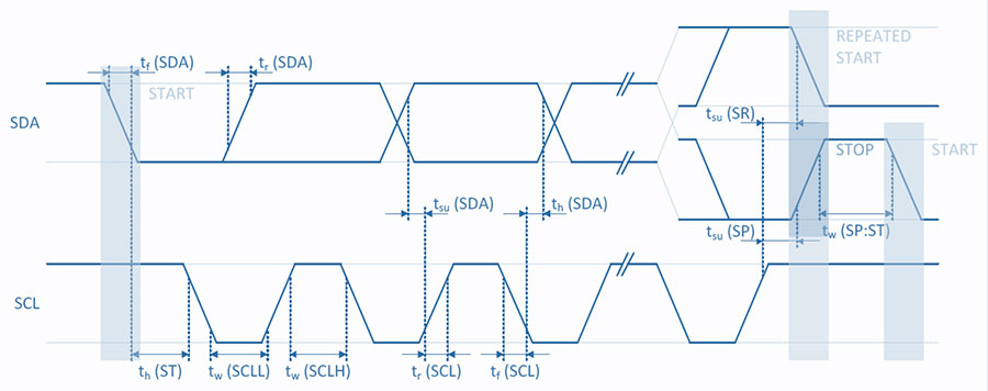
I2C Electrical Timing Characteristics
| I2C Standard | ||||
|---|---|---|---|---|
| Electrical Parameters | Symbols | Min | Max | Unit |
| SCL Clock Frequency | f(SCL) | – | 100 | kHz |
| SCL Clock Low Time | tw(SCLL) | .47 | μs | |
| SCL Clock High Time | tw(SCLH) | 4.0 | μs | |
| SDA Setup Time | tsu(SDA) | 250 | μs | |
| SDA Data Hold Time | th(SDA) | 3.45 | μs | |
| SDA and SCL Rise time | tr(SDA), tr(SCL) | 1000 | μs | |
| SDA and SCL Fall Time | tr(SDA), tr(SCL) | 300 | μs | |
| START Condition Hold Time | tr(ST) | 4 | μs | |
| REPEATED START Condition Setup Time | tsu(SR) | 4.7 | μs | |
| Stop Condition Setup Time | tsu(SP) | 4 | μs | |
| Bus Free Time Between STOP and START Condition | tw(SP:ST) | 4.7 | μs | |
Product Function Overview:
The Rochester Sensors 9705 module can be attached to any R3D dial face to detect the fluid level indicated. The sensor accomplishes this by detecting the position of the level indicator along an X and Y axes. The output of the module is proportional to this positional data. Users must connect a processing device to the 9705 module that can communicate via I2C protocol and interpret the raw data. The output from the module must be converted into an angular format and used in conjunction with look-up tables to produce the level percentage of the dial it is installed on. 9705 modules use a 4-wire cable to connect to the users monitoring system: 3VDC supply, ground, and two communication wires for the I2C bus.
Reading from Sensor:
The users monitoring device must utilize a “master” controller which can talk to the “agent” IC inside the 9705 R3D module. The master device drives the SCL clock line and initiates the data transfer over the I2C bus. The 9705 module can then respond to the master device with the raw positional data it collects from the corresponding Rochester Sensors R3D dial. The 9705 module also provides local temperature data during this process. To begin, users must initialize the device by setting gain and resolution, and enabling continuous operating mode. The controller must then issue a start sequence on the I2C bus to begin data transaction with the 9705 module. Data is transferred to/from the sensor in sequences of 8 bits. The users monitoring device must be able to process the raw X and Y positional data being received from the 9705 module into an angular format. The controller will need code and look-up tables to convert the angular output to a tank volume that can be used in conjunction with the end application.
Pseudo Code:
	#include
	#include

void main() {

	/* Initialize sensor */
	// set gain to 3, set configuration to 0x0c
	sensor_set_gain_hallconf(3, 0x0c);
	// set channel resolution to 3 for X, Y and Z axis
	sensor_set_resxyz(3);
	// set device in continuous operating mode
	StartBurstMode();

	// Loop to read sensor
	while (TRUE) {
		// read sensor X,Y,Z and Temperature
		sensor_measure(float &loTemp, int16 &loX, int16 &loY, int16 &1oZ);
		// convert cartesian to angle
		int16 loAngleDeg = get_ange_deg(1oX, 1oY);
		// convert angle to tank volume based on the tank physical shape and dial
		float tank_volume = convert_angle_to_level(loAngleDeg);
		// USER CODE TO DO SOMETHING WITH TANK VOLUME

	}
}
Measurement Mode (Burst Mode):
Typical configuration for the 9705 is to enable continuous ADC readings when the device is powered. Data is always available to the host microcontroller using this mode. An alternative method to issue a command to read data is available – contact Rochester Sensors for more information.
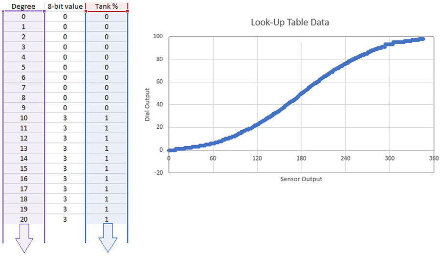
Dial Conversion formula:
Direction (y≥0, x>0) = [arcTAN(y/x)]*180/PI
Direction (y≥0, x>0) = 360 – [arcTAN(y/x)]*180/PI
Direction (y≥0, x<0) = 180 – [arcTAN(y/x)]*180/PI
Direction (y≥0, x<0) = 180 + [arcTAN(y/x)]*180/PI
Dial Look Up Tables:
9705 modules can be used in any R3D dial. Look-up tables for each dial offered by Rochester Sensors will be made available to all customers. The angular value should be calculated. This value can then be used along with the appropriate look-up table to interpolate a precise dial level indication.
Sample Table: Rochester Sensors 4” Magnetel Dial
Sample C-code:
Contact Rochester Sensors for sample C code for the 9705 module.
Warning: For LP-Gas and other flammable product service applications, connect only to circuits and power sources classified and labeled Intrinsically Safe for Class 1, Division 1, Group C and D hazardous locations. Connection of non-intrinsically safe power could result in fire or explosion of flammable vapor which may be present.
Warning: Sensor not to be used as the primary means of determining high or low fuel condition. It must not be used in the absence of redundant systems in critical applications where there may be significant safety risk or financial exposure in the event of fuel overfill or fuel exhaustion condition. This sensor is not to be used for tank filling.
Warning: Level Gauging devices and sensors sold by Rochester Sensors. are components only.
The purchaser/installer is solely responsible for the application of these components and ensuring all necessary steps have been taken to assure each application and use meets all performance and applicable safety requirements, and/or local, national and/or international safety codes as required by the application. Rochester Sensors. cannot certify that our products used solely or in conjunction with other Rochester Sensors. or other vendors’ products will assure desired performance and safety for any application.
Any person using or applying any products sold by Rochester Sensors. is responsible for learning the performance an safety requirements for their individual application and applying them, and therefore assumes, all risks, and accepts full and complete responsibility of the product for their respective application. Rochester Sensors. does not provide system design or consulting services, and cannot advise whether any specific application or use of our products would ensure compliance with
all performance and safety requirements for any application.
Hall Effect modules are intrinsically safe for Class 1, Division 1, Groups C & D Hazardous Locations. See SD-583 for control drawing. Protected by U.S. Patents.