Serie P6293
Eliminator 1 "medidores NPT para el reemplazo de Rotogauge en Bobtails, transportes y aplicaciones de almacenamiento masivo
Application
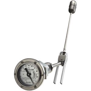
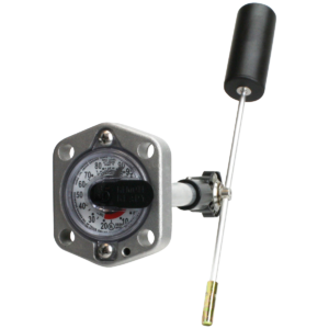
The Eliminator® direct-reading float gauge is a direct replacement for 1″ NPT rotary-type gauges in LP and NH3 storage tanks. These gauges are designed for larger tanks up to 84″ [2134mm] in diameter. The Eliminator® is not intended for use in filling tanks – its use is restricted to tanks with fixed liquid level gauges, used to determine when the maximum fill level has been reached. The eliminator can be used in mobile applications up to 72″ [1828mm] in diameter.
Documents
Data Sheet
MS-501/502 Installation Instructions
MS-516 Installation Instructions
| Número de pieza | Ajustar tamaño de tanque I.D. |
|---|---|
| Estacionario/móvil P6293-R4400 | Hasta 44 "[1210] |
| Estacionario/móvil P6293-R6000 | 44,1 "Thru 60" [1210]-[1524] |
| Estacionario P6293-R7200 | 60,1 "Thru 72" [1524]-[1829] |
| Móvil P6293-R7200 | 60,1 "Thru 72" [1524]-[1829] |
| Estacionario P6293-R8400 | 72,1 "Thru 84" [1829]-[2134] |
Any Eliminator installed in a tank greater than 44” is excluded from the Rochester Gauge Limited Warranty.
THESE INSTRUCTIONS ARE PREPARED TO ASSIST TRADESMEN AND OTHERS QUALIFIED TO SERVICE LIQUID STORAGE TANK EQUIPMENT. CONSUMERS ARE NOT QUALIFIED TO PERFORM THE INSTALLATION DESCRIBED BELOW. IF YOU HAVE ANY QUESTIONS CONCERNING INSTALLATION OR OPERATION OF THE GAUGE OR GASKET, CONTACT Rochester Sensors. OR ONE OF OUR AUTHORIZED DISTRIBUTORS FOR ASSISTANCE. CHECK SIDE OF GAUGE HEAD FOR MODEL NUMBER AND ASK FOR GAUGE INSTALLATION INSTRUCTIONS FOR YOUR MODEL.
Cómo hacer la conversión
1. después de evacuar el tanque de almacenamiento, quite el medidor rotativo de la abertura de 1 "NPT en la línea central de la cabeza. Limpie y vuelva a tocar las roscas femeninas.
2. Extraiga los dos tornillos del bisel. Coloque el bisel, los tornillos y la cámara de marcación a un lado por el momento. Quite los cuatro tornillos de montaje que sujetan el cabezal del medidor al adaptador.
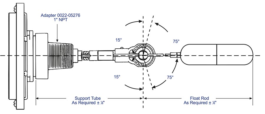
3. Inserte la porción inferior del medidor de reemplazo, incluyendo la bombilla flotante, el brazo flotante, la carcasa del engranaje y el contrapeso, en la abertura del tanque.
4. Aplique tres envolturas de 1 ⁄ 2 "[12mm] cinta de teflón ancha, u otro sellador de rosca adecuado, a las roscas de 1" NPT en el adaptador de acero a través del cual el medidor de soporte pasa.
5. Atornille el adaptador en la abertura del tanque para lograr una articulación hermética y alinee los orificios de montaje del medidor en el plano horizontal.
6. con la Junta y los cuatro tornillos de montaje suministrados, fije el medidor al adaptador con el dedo. Asegúrese de que el medidor está a la derecha hacia arriba, la lengüeta de soporte para ubicar la cámara de marcación debe estar a la derecha. Par los tornillos de montaje uniformemente a 140/150 lb.in., [16, 4Nm] utilizando un patrón cruzado.
7. Vuelva a conectar la cámara de dial y el bisel de 4 "a los soportes de cabeza de calibre Senior® utilizando los dos tornillos suministrados.
8. Si termina con la cámara de marcación boca abajo, no puede resolver el problema girando el soporte. Debe rotar todo el medidor 180 °.
WARNING: Even if gauge registers empty, tank may contain high pressure and flammable gas. Do not remove gauge or other pressure containing fittings unless precautions against release of tank contents have been taken. A hazard of fire or explosion may exist if proper methods are not used when removing or installing the gauge or gasket. Replace gasket if gauge is removed. Do not reuse gasket. When reinstalling gauge head align head for proper orientation of the float inside tank. Torque head or mounting screws evenly in several steps based on mounting screw size, gasket material & gauge head size & style.
CAUTION: Improper gauge selection or application may result in inaccurate gauge readings. Release of tank contents as well as damage to equipment and safety hazard may result if tank is overfilled. Fuel exhaustion may occur if tank contents are less than indicated. This gauge is not a substitute for a fixed liquid level gauge or weight measurement device that may be required for filling.
WARNING: Improper APPLICATION, installation, or use of this gauge may cause serious injury or property damage.
Materiales de construcción *
Head, Gears, Gear Housing, Cros Stud, Bearings & Float
Stainless steel.
Centershaft, Support Tube & Float Rod
Stainless steel.
Drive Magnet
Alnico.
Gasket
Spiral wound, teflon filled, stainless steel.
Adaptor
Cold-rolled steel.
Counterweight
Stainless Steel
Al ordenar especifique:
1. Gauge model number.
2. Tank I.D.
WARNING: Carefully ensure that gauge and adapter are adequately protected from damage that might cause leakage of tank contents.
* Los materiales y especificaciones están sujetos a cambios sin previo aviso. Las clasificaciones de presión están sujetas a cambios debido a la temperatura y otras consideraciones medioambientales.