P6293 Series
Eliminator 1” NPT Gauges for Rotogauge Replacement in Bobtails, Transports and Bulk Storage Applications
Application
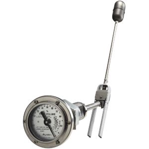
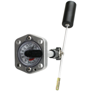
The Eliminator® direct-reading float gauge is a direct replacement for 1″ NPT rotary-type gauges in LP and NH3 storage tanks. These gauges are designed for larger tanks up to 84″ [2134mm] in diameter. The Eliminator® is not intended for use in filling tanks – its use is restricted to tanks with fixed liquid level gauges, used to determine when the maximum fill level has been reached. The eliminator can be used in mobile applications up to 72″ [1828mm] in diameter.
Documents
Data Sheet
MS-501/502 Installation Instructions
MS-516 Installation Instructions
| Part Number | Fit Tank Size I.D. |
|---|---|
| Stationary/Mobile P6293-R4400 | Up to 44″ [1210] |
| Stationary/Mobile P6293-R6000 | 44.1″ thru 60″ [1210]-[1524] |
| Stationary P6293-R7200 | 60.1″ thru 72″ [1524]-[1829] |
| Mobile P6293-R7200 | 60.1″ thru 72″ [1524]-[1829] |
| Stationary P6293-R8400 | 72.1″ thru 84″ [1829]-[2134] |
Any Eliminator installed in a tank greater than 44” is excluded from the Rochester Sensors Limited Warranty.
READ COMPLETELY WARNINGS & CAUTIONS BEFORE ATTEMPTING GAUGE REMOVAL OR INSTALLATION*THESE INSTRUCTIONS ARE PREPARED TO ASSIST TRADESMEN AND OTHERS QUALIFIED TO SERVICE LIQUID STORAGE TANK EQUIPMENT. CONSUMERS ARE NOT QUALIFIED TO PERFORM THE INSTALLATION DESCRIBED BELOW. IF YOU HAVE ANY QUESTIONS CONCERNING INSTALLATION OR OPERATION OF THE GAUGE OR GASKET, CONTACT Rochester Sensors. OR ONE OF OUR AUTHORIZED DISTRIBUTORS FOR ASSISTANCE. CHECK SIDE OF GAUGE HEAD FOR MODEL NUMBER AND ASK FOR GAUGE INSTALLATION INSTRUCTIONS FOR YOUR MODEL.
How To Do The Conversion
1. After the storage tank has been evacuated, remove the rotary gauge from the 1″ NPT opening at the centerline of the head. Clean and retap the female threads.
2. Remove the two screws from the bezel. Put the bezel, screws and dial chamber aside for the moment. Remove the four mounting screws holding the gauge head to the adapter.
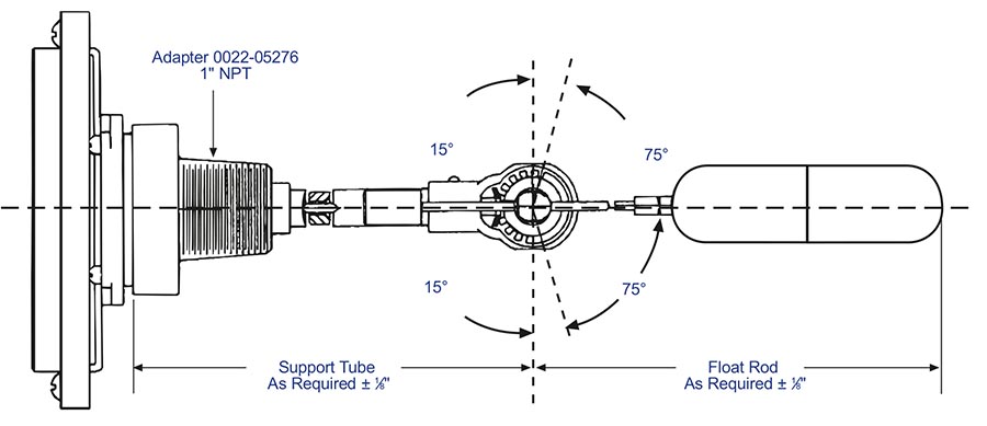
3. Insert the lower portion of the replacement gauge, including the float bulb, float arm, gear housing and counterbalance, into the tank opening.
4. Apply three wraps of 1⁄2″ [12mm] wide Teflon tape, or other suitable thread sealant, to the 1″ NPT threads on the steel adapter through which the gauge support passes.
5. Screw the adapter into the tank opening to achieve a leak-tight joint, and align the gauge mounting holes in the horizontal plane.
6. Using the gasket and four mounting screws supplied, attach the gauge to the adapter fingertight. Be sure the gauge is right side up, the bracket tab for locating dial chamber should be on the right. Torque the mounting screws evenly to 140/150 lb.in., [16,4Nm] using a cross pattern.
7. Reattach the 4″ dial chamber and bezel to the Senior® gauge head brackets using the two screws supplied.
8. If you end up with the dial chamber upside down, you cannot solve the problem by rotating the bracket. You must rotate the entire gauge 180°.
WARNING: Determine and install the appropriate replacement gauge based on system requirements. The gasket type supplied may not be suitable for all applications and for those applications other gasket materials may be available. The information contained herein is intended for guideline use only and the suitability of any part for a particular application must be determined by the user prior to installation. Improper gauge or gasket selection or application may result in seal failure and subsequent release of tank contents.WARNING: Even if gauge registers empty, tank may contain high pressure and flammable gas. Do not remove gauge or other pressure containing fittings unless precautions against release of tank contents have been taken. A hazard of fire or explosion may exist if proper methods are not used when removing or installing the gauge or gasket. Replace gasket if gauge is removed. Do not reuse gasket. When reinstalling gauge head align head for proper orientation of the float inside tank. Torque head or mounting screws evenly in several steps based on mounting screw size, gasket material & gauge head size & style.
CAUTION: Improper gauge selection or application may result in inaccurate gauge readings. Release of tank contents as well as damage to equipment and safety hazard may result if tank is overfilled. Fuel exhaustion may occur if tank contents are less than indicated. This gauge is not a substitute for a fixed liquid level gauge or weight measurement device that may be required for filling.
WARNING: Improper APPLICATION, installation, or use of this gauge may cause serious injury or property damage.
Materials of Construction*
Head, Gears, Gear Housing, Cros Stud, Bearings & Float
Stainless steel.
Centershaft, Support Tube & Float Rod
Stainless steel.
Drive Magnet
Alnico.
Gasket
Spiral wound, teflon filled, stainless steel.
Adaptor
Cold-rolled steel.
Counterweight
Stainless Steel
When Ordering Specify:
1. Gauge model number.
2. Tank I.D.
WARNING: Carefully ensure that gauge and adapter are adequately protected from damage that might cause leakage of tank contents.
*Materials and specifications are subject to change without notice. Pressure ratings subject to change due to temperature and other environmental considerations.