7200 Series
1 ¼” MPT Gauge for Domestic Tanks
Application
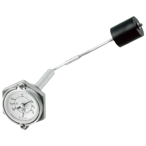
The 7200 and B7200 Series Junior™ gauges are identical except the former has a zinc die-cast head and the latter has a forged-brass head. Both types have 1 ¼” Male NPTF threads and 2” [51] hex-wrenching sections and are equipped with direct-reading dials appropriate for the tanks in which they are installed.
General Information & Features*
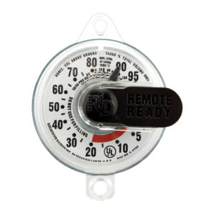
Model 7281 and B7281 direct-indicating gauges are for top mounting. When used on above-ground ASME, horizontal, domestic storage tanks, they are equipped with 5323S01749 percentage or 5323S01789 fractional dials. When used on tanks buried underground, they are equipped 5323S01813 percentage dials. Most 420# [190kg] vertical cylinders utilize the 5323S01835 dial. For dials used on other vertical cylinders, contact Rochester.
Model 7284 and B7284 gauges are for side, end or angle mounting. When used on ASME motor-fuel tanks they are equipped with 5323S01789 fractional dial.Please contact Rochester for the part numbers of the various dials used on gauges mounted in lift-truck cylinders.
Model 7241 (top mounting) and 7244 (side-end-or angle mounting) gauges incorporate a stronger magnet required to drive TwinSite™ senders in motor-fuel applications. These gauges can be furnished less dial with 5323S01789 fractional, direct-indicating dials or with the appropriate TwinSite™ sender, P5628S0537, 0- 90Ω, or P5663S02527,20-150Ω as required.
Documents
Data Sheet
General Specifications*
Temperature Range
Standard range is 40°F to 158°F,-40C to 70C.
Accuracy
Dependent on proper sizing of gauge and tank configuration. With direct reading dials, overall accuracy is ±5%; with TwinSiteTM Sender, ove- rall accuracy is ± 5%.
Current
TwinSiteTM versions, 200 mA. Maximum
Voltage
24 volts maximum nominal system voltage on TwinSiteTM versions.
Working Pressure
375 psig [25,8 Bar].
Approvals
Gauges are appropriately UL listed for LP Gas liquid-level service and/or LP Gas automotive accessories
When ordering, specify:
1.The tank inside diameter (shown on tank nameplate). 2. The mounting location (top, side, end or angle).
3.If the gauge is angle mounted state the degree of angle above or below the horizontal centerline.
4.If the gauge is end mounted, state the shape of the tank head (hemispherical or semi-ellipsoidal).
5.The ‘’H’’ dimension. This is the distance in inches from the surface of the tank to the top of the top threaded opening.
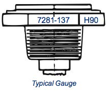
To order replacement gauge, simply furnish the information Stamped on one of the heads, as shown in the example.
Typical gauge head showing part number or tank code and Date code stamped on wrenching flats shown to the right.
Materials of Construction*
Head
Zinc die casting (7200 Series); brass forging (B7200 Series).
Centershaft Bearings, Gears, Pinion, Cross Stud & Bearing
Stainless Steel.
Gear Housing
Zinc die-casting or acetal.
Support, Centershaft & Float Rod
Tempered aluminum.
Float Bulb
Nitrile rubber or one-piece aluminum.
Counterweight
Lead.
Magnets
Alnico
Standard, Direct Reading Dials
Hermetically sealed polycarbonate.
Dial Screws
Stainless steel.

*Materials and specifications are subject to change without notice. Pressure ratings subject to change due to temperature and other
Environmental considerations.


