D6342
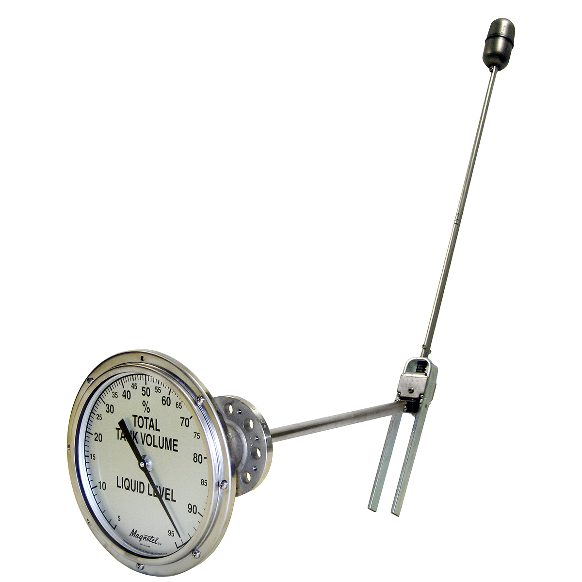
Magnetel® Gauge for Liquid CO2 Storage & Transport Applications
Application
This product is used to extend the dial chamber on any Magnetel® gauge away from the gauge head far enough to pass through the insulating jacket on tanks containing CO2, thus reducing refrigeration effects on the dial.
General Information & Features*
Gauge available in Trim 11, steel and stainless steel; and Trim 12, all stainless steel with enclosed magnet.
Dial in percent of total tank volume.
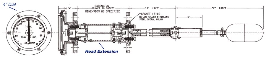
Length of epoxy glass laminated tube is available to specifications.
Stainless steel spiral wound teflon filled gasket.
For mobile applications specify model DM 6342. (Shown)
Documents
Data Sheet
6300 Series Standard Gauge Features data sheet
115-820 Magnetel® Installation Instructions
Special Installations Instructions DS-681 (see below)
* Materials and specifications are subject to change without notice.
Pressure ratings subject to change due to temperature and other environmental considerations.
DS-681 Instruction Sheet For Magnetel® Gauge with CO2 Extension
The purpose of the head extension is to extend the dial chamber from the gauge mounting flange. This insulates the dial chamber from the tank and allows for the insulating space between the inner tank and the outer shell.
Installation
The head extension is equipped with a plugged 1⁄8” N.P.T. hole in the bottom of the extension tube. Before installation of the gauge in the tank, this plug should be replaced with a tubing fitting. The tubing (1⁄4” minimum) should be routed to a convenient access point and then capped.
Trouble Shooting
If the gauge reading seems to be “stuck”, there are several possibilities: There may be a problem with the float mechanism inside the tank, a problem with the head extension or a problem with the dial chamber. Check the dial chamber first.
Dial Chamber Removal
Remove 8” dial chamber by removing the three screws located nearest the 9 o’clock, 3 o’clock and then the 12 o’clock positions. Remove 4” dial chamber by removing the two screws located nearest the 9 o’clock and 3 o’clock positions. After the dial chamber has been removed, DON’T disassemble.
Dial Chamber Test
Test dial chamber from the back side. You should be able to rotate the pointer easily by rotating the bar test magnet against the center back of the dial chamber. The Small Test Magnet has the appropriate magnetic properties for this test. If the pointer cannot be rotated freely, the dial chamber should be replaced.
PLEASE NOTE: Bent dial brackets can cause the pointer to bind when the dial chamber is re-installed. Be sure brackets are not bent. If the dial chamber is functional, the next test is for the head extension.
Head Extension Test
With the dial chamber removed, place the large test magnet in the center of the dial chamber recess on the exposed portion of the head extension. This recess is about two inches in diameter and about 3⁄8” deep. The Large Test Magnet has the appropriate magnetic properties for this test. Rotate the large test magnet slowly one complete revolution. The large test magnet should overpower the drive magnet in the tank and rotate the magnet and shaft assembly in the head extension. If the magnet and shaft assembly in the head extension is frozen, the large test magnet will be repelled by the non-rotating magnet in the head extension. This repelling force will try to push the large test magnet out of the recess as it is rotated. If the CO2 extension is frozen, the corrective action is drying. If the extension is functional, proceed to “float mechanism”.
Drying
Drying the inside of the head extension is usually done by injecting a dry gas such as nitrogen. The gas is injected by inserting a l⁄8″ or 5⁄32″ diameter plastic supply tube inside the 1⁄4″ access tube that is attached to the head extension. Be sure that the small tube goes completely inside the extension and that the exhaust gas can pass through the annular space between the outside of the supply tubing and the inside of the access tubing.
This process works best if the temperature of the head extension can be raised above the freezing point of water. One way to do this is to warm the flowing gas before it reaches the CO2 extension. Another way is to wrap the extension with a water pipe heating strip. After the head extension has thawed and dried, retest using the large magnet. If the function seems satisfactory, allow the temperature of the head extension to return to the normal below freezing condition. Retest the head extension again using the large test magnet.
Float Mechanism
If the head extension seems to be functioning properly, the next test is for the gauge and float mechanism inside the tank. For this test you will need to replace the dial chamber. Before bolting the dial chamber to the mounting brackets, be sure that all brackets touch the dial chamber without the dial chamber rocking. If the dial chamber does not fit properly, one or more of the dial brackets may be bent and should be replaced. Once the dial chamber has been replaced, take steps necessary to produce a significant change in the level of the product inside the tank. If the pointer does not move, then the problem may be in the gauge mechanism inside the tank. If this seems to be the case, then follow the trouble shooting guide for the gauge. This guide is located in bulletin 115-820.
If the gauge function is still not satisfactory after following the trouble shooting guide, then the entire gauge including head extension and dial chamber should be returned to the factory for overhaul, adjustment and re-lubrication of the head extension.
SPECIAL REQUIREMENTS FOR TESTS:
1. Small Test Magnet – 1⁄16” DIA x 1⁄2” Neodymium Rod Magnet.
2. Large Test Magnet – 1⁄2” DIA x 3⁄4” Neodymium Rod Magnet.
3. Bulletin 115-820
The test magnets may be obtained from: http://www.kjmagnetics.com